By the myPitLab team · Last updated 28 July 2026 · 8 min read
TL;DR
- Trial pits need a dedicated data structure; a manhole form or generic photo folder is not enough.
- Record each exposed service independently with material, diameter, depth, direction and confidence.
- Link soil strata, excavation geometry, coordinates and photo evidence to one trial pit ID.
- Ground control points and survey observations can align the 3D model to project coordinates.
- Publish one verified pack containing the report, photos, CAD/GIS data and interactive model.
Why trial pit records become difficult
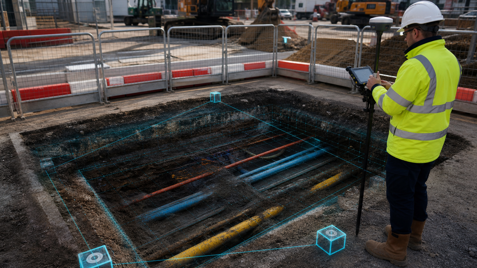
A trial pit can expose several utilities at different levels, surrounded by changing soil layers and temporary excavation geometry. Teams often collect this information across:
- A site notebook
- Phone photographs
- A CAD sketch
- A spreadsheet
- Survey controller files
- A separate Word report
When identifiers or depths differ between those sources, office staff spend hours reconstructing what happened on site. Trial pit survey software should make the pit—not the file—the central record.
Information to capture for every trial pit
Location and control
Record:
- Unique TP identifier
- Easting and northing
- Ground level or project datum
- Coordinate reference system
- Survey method and instrument
- Accuracy or confidence statement
Device GPS is useful for initial context, but final coordinates may come from GNSS, a total station or established site control.
Excavation geometry
Capture length, width, depth, orientation and side slopes where relevant. If the excavation changes during work, preserve the inspection time and stage.
Exposed services
Each service should have its own record:
- Service type
- Material
- Diameter or dimensions
- Top and bottom levels where observed
- Depth below ground
- Direction
- Condition
- Identification method and confidence
Do not combine multiple services into one free-text note. Structured service records are easier to validate, export and compare with utility drawings.
Ground and strata
Trial pits frequently provide geotechnical context. Record the sequence of visible materials, approximate thickness, groundwater, made ground and notable inclusions. Keep factual observations separate from interpretation.
Photographs
At minimum, capture:
- General pit context
- Each exposed service
- Measuring device or staff where required
- Strata and excavation walls
- Ground control or survey setup
- Reinstatement or final condition
Use geo-photo capture so location, time and asset ID remain attached.
Turning the pit into a 3D record
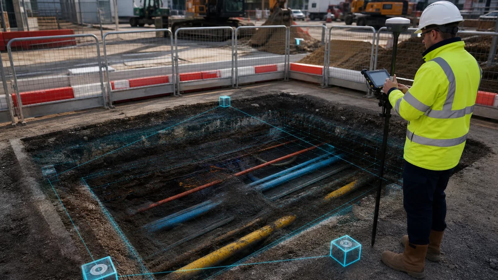
LiDAR or photogrammetry can create a useful visual model of the excavation. The model helps clients understand vertical separation and congestion between utilities, particularly when several services cross.
For a defensible model:
- Capture stable ground around the excavation.
- Include visible targets or control points.
- Photograph all sides with overlap.
- Record independent service depths.
- Assign known X, Y and Z values to control points.
- Compare model dimensions with field measurements.
The raw model should remain preserved. Calibration creates a verified transform and scale with its own audit information.
GCPs for trial pit models
Three or more well-distributed points can constrain position, orientation and scale. Avoid putting every point on one straight edge. Where possible, distribute control across the pit perimeter and include vertical variation.
GCP verification should display residuals or differences so the reviewer can judge whether the fit is acceptable. A green status badge is not enough without numbers and context.
QA checks before client delivery
Use a publish gate that checks:
- TP ID matches schedule and filenames
- Coordinates and CRS are present
- Ground level or datum is defined
- Service count matches photographs
- Depth reference is clear
- Units are consistent
- GCP or scale status is recorded
- Required photographs exist
- Model limitations are stated
- CAD and GIS attributes use the same IDs
The principles mirror MH and IC publish QA, but the fields are specific to trial pits.
Client handover formats
A complete trial pit handover may contain:
- A4 PDF inspection sheets
- Project summary
- Original and annotated photographs
- CSV service schedule
- DXF plan and section
- KML/KMZ location data
- Interactive 3D model
- Model file or point cloud where contracted
The PAS128 report guide explains how methodology, limitations and confidence should remain visible in the wider project report.
Trial pits in the client portal
A client should be able to select TP-024 on a map and immediately see:
- Current status
- Service observations
- Photographs
- 3D model
- QA history
- Downloads
- Previous revisions
That experience is more useful than a ZIP containing files with similar names. It also reduces the risk that a superseded report is treated as current.
Frequently asked questions
Is trial pit software only for PAS128 work? No. It is useful for design verification, service crossings, foundation exposure, drainage investigations and construction records.
Can phone coordinates be used? They provide context, but project deliverables may require survey-grade control. Record the source and expected accuracy.
Can a trial pit model show individual services? Yes. Services can be represented as separate objects with type, material, diameter and measured levels.
Should the 3D model replace the section drawing? Usually not. The model supports understanding; a controlled section and structured schedule remain important contractual outputs.
Summary
Good trial pit survey software connects excavation geometry, exposed services, strata, coordinates, control, photographs and reporting. The result is a verified project record instead of a collection of files that the office must reconcile manually.
Explore field capture and digital twin delivery in myPitLab →